
Signal Enhancement - Geotizer
See seismic data as it was meant to be seen. It models and removes linear coherent noise without damaging your signal or smearing amplitudes. The outcome? A massive boost in signal-to-noise ratio, preserved amplitude integrity, and a cleaner frequency spectrum – all for your 2D and 3D volumes. Get the clearest, most interpretable seismic data possible."
GEOTIZER Basic Concept
Tired of noise blurring critical geological details in your seismic data? Geotizer tackles the core challenge: separating signal from noise.
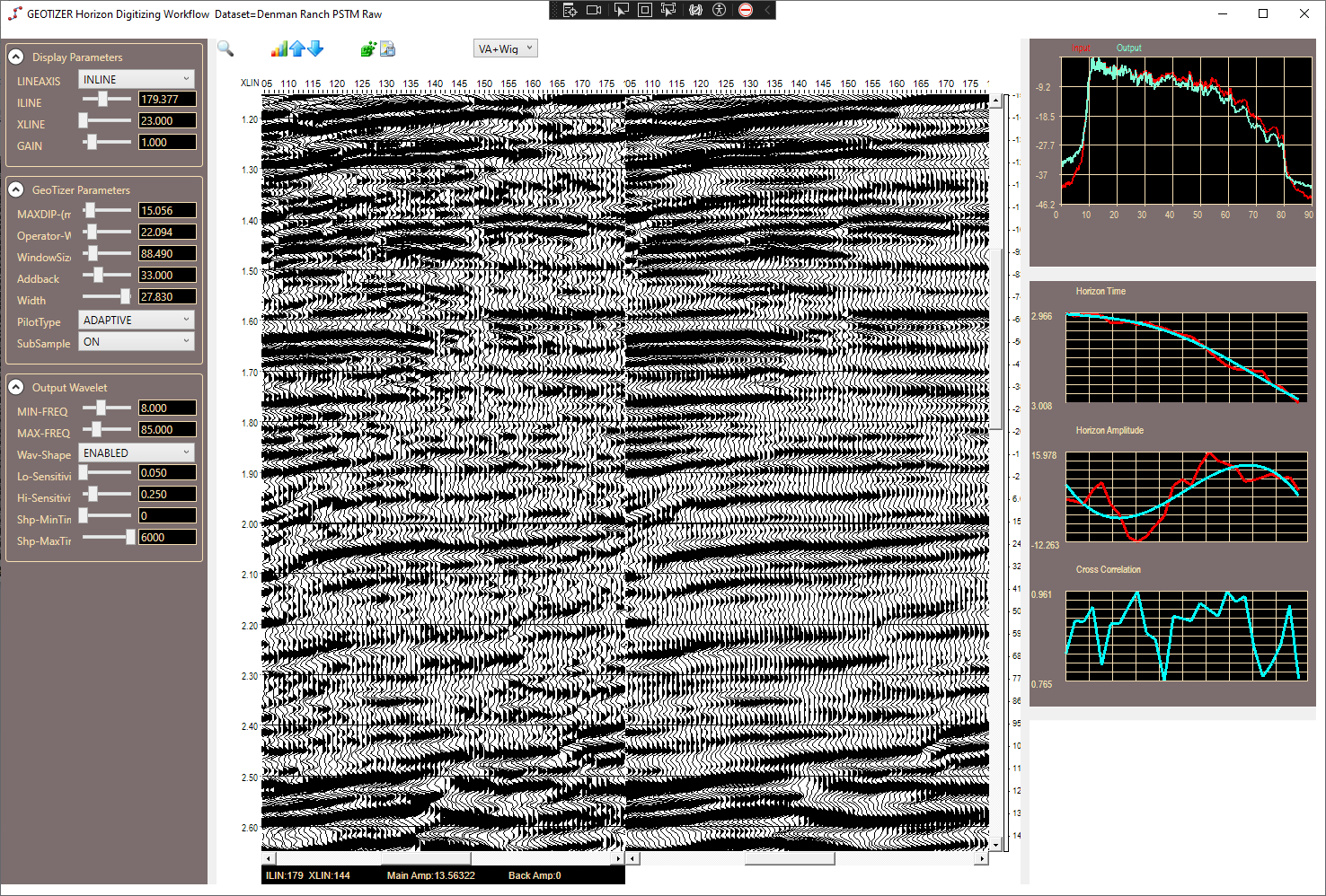
The Geotizer models every single sample in a volume as a probability in a small local paraboloidal modeled sequence of reflections. A small cube around each sample is transformed into the FXY domain along parabolic trajectories along the X and Y axis, a noise filter is applied, and the resulting amplitude information is extracted.
The Geotizer
Introducing the Geotizer: The industry-leading solution for pristine seismic data. Geotizer precisely models both your valuable reflection signals and troublesome linear coherent noise. This unique understanding allows it to directly design and apply the optimal inverse filter at each reflective interface. The result? Unprecedented signal-to-noise ratio improvement, with flawless amplitude preservation and no frequency smearing. Geotizer delivers hyper-clear 2D and 3D seismic volumes, revealing subtle features obscured by noise and boosting the confidence of every interpretation.
By modeling noise with parabolic trajectories alongside reflections in the frequency / x / y (fxy) domain, Geotizer performs a spatial deconvolution to pinpoint the ideal inverse filter to remove the noise within the frequency domain. This means significantly enhanced signal clarity, better preserved amplitudes crucial for amplitude analysis in petrophysical analysis, and improved frequency content. Experience the game-changing difference of crystal-clear seismic data for both 2D and 3D volumes, leading to better reservoir characterization and exploration success.

Parabolic Transform (Frequency Domain)
Let f(t) be the input signal in the time domain, and F(ω) be the transformed signal in the frequency domain.
Forward Transform:
The parabolic transform in the frequency domain can be represented by the following equation:
This equation applies a quadratic phase modulation to the signal before performing the standard Fourier transform.
Inverse Transform:
To reconstruct the original signal from its parabolic transform:
Where:
- f(t): Original signal in time domain
- F(ω): Transformed signal in frequency domain
- t: Time variable
- ω: Angular frequency
- i: Imaginary unit
- iωt: Quadratic phase term

Breathe new life into old data...
Check out this example of a reasonably well processed 3D with a small salt layer with an Anhydrite Cap causing a transmission loss and the weakened structural detail below is masked with migration artifacts.
The Geotizer models and subtracts the linear coherent energy caused by data processing artifacts and environmental noise sources that manifest as linear coherent noise trains.
Do you have 2D or 3D data that could use a facelift?
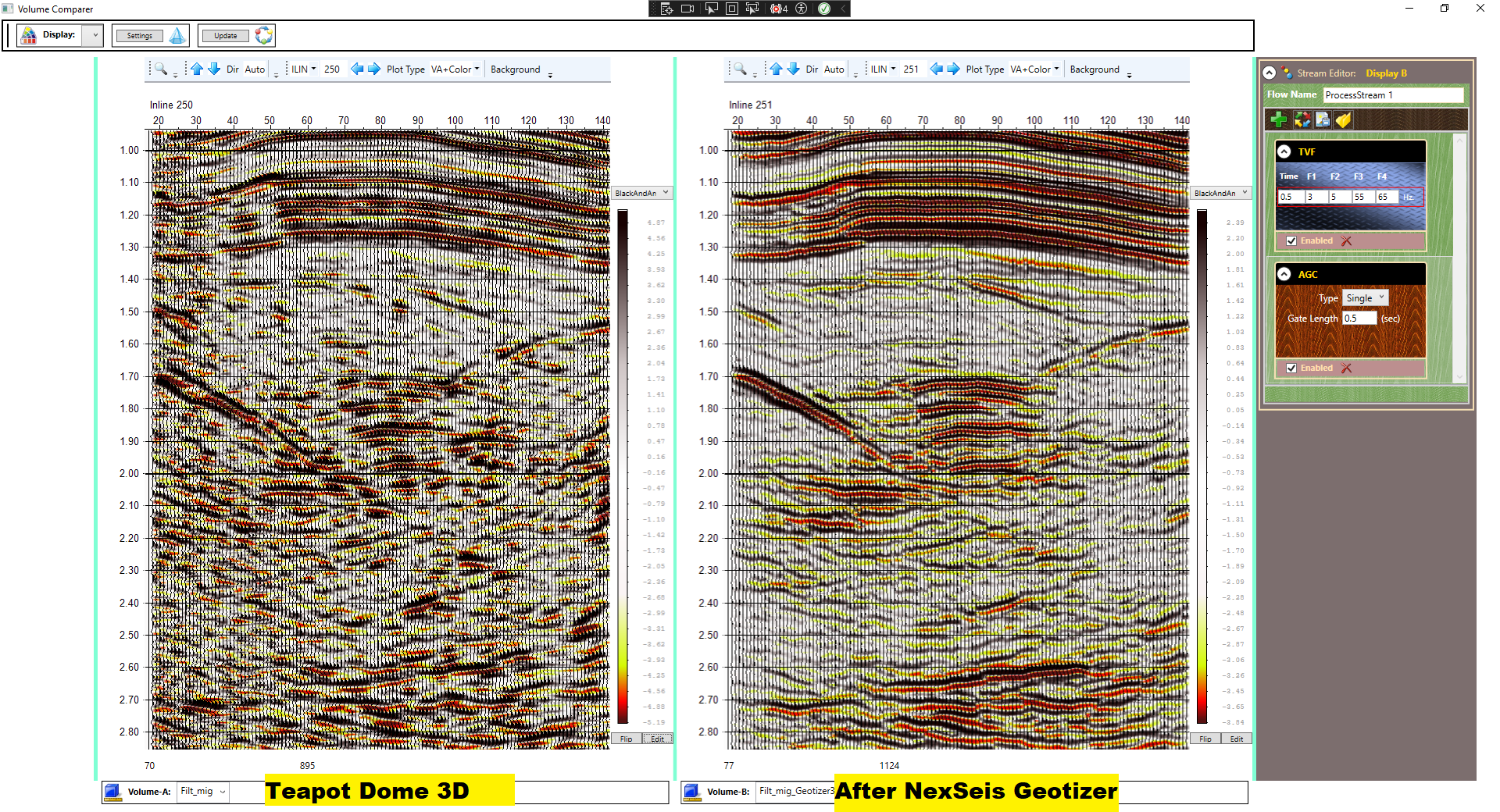
The image on the left is the off the shelf Teapot Dome 3D survey processing, with the image on the right after the NexSeis Geotizer application. By modeling and removing linear coherent noise, faults are clearer and entire depositional sequences are visible and or much cleaner and even interpretable. If you are having trouble mapping horizons or just making sense out of the big picture in your seismic data, a highly affordable alternative is available relative to the cost of reprocessing your data.